5 Ways to Create a Simple Yet Effective Part Drawing
Over the years, we’ve seen thousands of part drawings come through our Idaho machine shop. As technology evolves, we’ve recently noticed something new about many RFQs we receive: drawings that are polished but sometimes more detailed than necessary.
Today’s CAD tools make it easy to auto-generate prints and dimension edges, angles, and holes. But now, many drawings we receive include so many callouts that they end up increasing the cost of the part, often without the customer realizing it.
At Accurate CNC, we want to help you get the most out of your precision CNC machining services. That starts with a drawing that communicates what matters without potentially increasing your costs.
Here are our top tips for creating a part drawing that’s simple, effective, and easy on your budget.
1. Don’t Let CAD Tools Overdo It
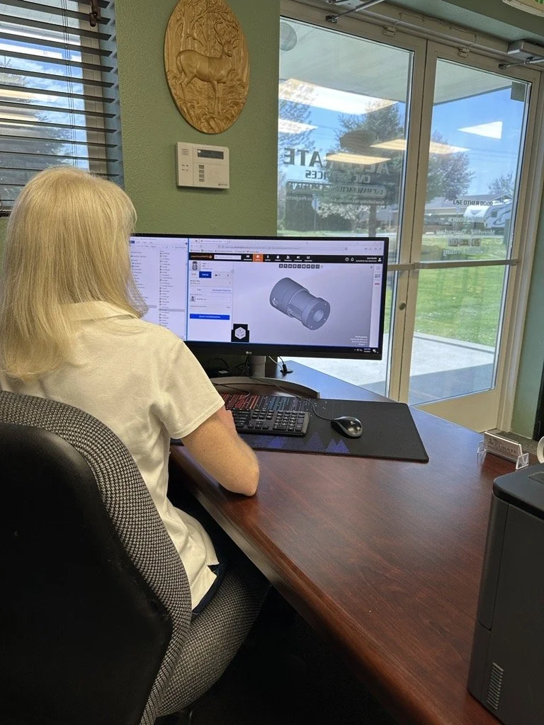
CAD programs like Fusion 360, AutoCAD, and SolidWorks are powerful, and automatic drawing generation features can be a huge time-saver. But left unchecked, they often create prints with more detail than the part actually needs.
Every dimension becomes a point of inspection, which in turn drives up your machining and quality control time. We’ve seen many examples of dimensioning that is well-intentioned but more detailed than necessary, like every edge radius labeled on parts that don’t require it.
What to do instead: After generating your part drawing, do a quick once-over. Ask yourself: Do I need every feature verified? Is this tolerance meaningful to how the part will function? Trimming the fat on your drawing won’t hurt your part, but it will save you money and time.
2. Only Use Tight Tolerances When Necessary
While we’re always ready to handle your precision projects, we sometimes see drawings with tight tolerances on features that turn out not to require them.
Take hardware holes, for example. If you’re just dropping a bolt through, a looser tolerance is almost always acceptable. When simple holes are speced with tight callouts, these parts require a more intensive inspection process involving gauge pins and extra setup. That process leads to additional time and cost.
What to do instead: Save tight tolerances for parts that truly need them, like press fits, alignment features, or components with moving interfaces. If a fastener is just passing through or anchoring into a tapped hole, you can typically let the part’s function guide the precision.
3. Use Dimensions That Allow Efficient Inspection
Our Idaho machine shop recently received a part drawing that looked fine at first glance, until we noticed every hole location was dimensioned in degrees, which required us to build a jig to check those angles. Simple linear dimensions likely would have been sufficient for the part’s application, saving the customer labor costs in their final price.
What to do instead: Whenever you can, dimension things in a way that’s straightforward to verify with common tools. Hole-to-hole distances, centerlines, and edge offsets are all faster and more practical than angular setups. You don’t need to change your whole process, just take a moment to ask, “Would this be easy to check on a CMM or with a tape measure?” If not, it might be worth adjusting.
4. Don’t Forget the Basics
One common issue we see is when the basics are missing from a drawing. Features such as overall length, width, thickness, and hole quantity can be understandably overlooked when you're focused on more complex aspects. But without them, your project can’t get started until a few additional questions are answered.
It’s the same with the bill of materials and assembly notes. If you’re including hardware, details such as part numbers, quantities, or special instructions can help ensure everything comes together as intended.
What to do instead: Start by making sure the key dimensions like length, width, thickness, and hole locations are clearly included. From there, think about how the part will actually be built. Are there features that need to align with another component? Is there hardware that requires a countersink or a specific insert? Those are the kinds of details worth calling out.
And if you have special assembly instructions, a simple note will do the trick. It doesn’t have to be overly technical, it just needs to be clear.
5. Dimension With Part Function in Mind
One of the best ways to simplify your drawing is to step back and consider how the part will be used. A door panel, cover plate, or riser block usually doesn’t require extensive callouts or tight tolerances. However, if the part is critical to alignment or fit, it makes sense to be more detailed.
This is where over-dimensioning often happens. CAD tools make it easy to include every possible callout, and AI-assisted features sometimes default to tighter specs than necessary. You may simply be trying to be thorough, but those extra details can unintentionally add time and cost.
What to do instead: Before finalizing your part drawing, take a moment to ask: Does this feature need to be called out? Will this tolerance make a difference in how the part functions? If you're unsure, your machine shop can help you determine what matters and what doesn't. A quick conversation upfront can go a long way toward keeping your project on time and on budget.
Let Us Help You Save
CAD tools can be extremely helpful, but they don’t always prioritize what’s most important for efficient, cost-effective machining. A quick review of your part drawing can help you catch missing details, trim unnecessary callouts, and keep your project moving forward.
If you’re working on a new project and want to make sure your drawing is on the right track, we’re happy to take a look. Whether you’re in the early stages of prototyping or moving into production, we can help you stay within budget and ensure your parts are made right the first time.
Have a project ready to go? Request a quote and let’s get started.


